Arduino music using Direct Digital Synthesis
This page is a brief introduction to the use of an Arduino micro-controller board to make beautiful musical music, starting with a basic square wave generator, all the way to a wavetable synthesizer which can play chords of up to 8 notes.
All this without any external hardware (except for whatever speaker / amplifier / headphones you choose to hook up), and only using a single output pin on the arduino.
Simple square wave sound generation
Arduinos are a digital device. So, in output mode, each pin can output a zero (0v) or a 1 (5v).
If we connect the pin to a speaker, when the pin is 0, the speaker will move one way, and when the pin is 1, it will move all the way the other way. Note: if you’re just starting, I’d recommend using a simple piezo sounder, they are cheap, and can be connected directly to an Arduino digital pin. Later on, you’re likely to want more volume and a nicer tone, which will need some kind of amplifier, or going to headphones or an external amplifier. See my arduino amplifier instructions for more details of that
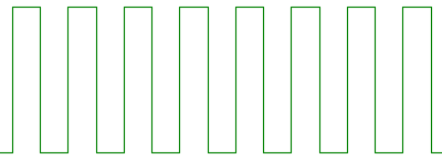
Anyway, assuming we have a pin connected to a speaker or piezo sounder, if we repeatedly change from zero to one and back very quickly, the speaker will output what is known as a square wave. Changing how fast the value changes from zero to one alters the frequency or pitch of the note that is played - for example if you change from zero to one and back 440 times a second, the frequency will be 440Hz, or the A above middle C, used for tuning orchestral instruments.
A Square Wave
The following code simply uses the arduino’s ‘delaymicroseconds’ function in order to play a square wave with the pitch of A 440hz, on digital pin 11.
// A440Test
    // Play square wave with pitch A 440hz
    // output is to a speaker,
    // piezo buzzer or whatever,
    // connected to pin 11

    void setup()
    {
        // pin 11 is
        // connected to our speaker
        pinMode(11, OUTPUT);
    }

    void loop()
    {
        digitalWrite(11, HIGH);   // set output to 5 volts
        delaymicroseconds(1136);  // wait for an 880th of a second
        digitalWrite(11,

LOW);    // set output to 0 volts
delaymicroseconds(1136);  // wait for an 880th of a second
}
Play A440 Square Wave using delaymicroseconds
It’s pretty trivial to alter this code to make it play tunes, or alter pitch based on an analog input, or whatever. The good news however, is that you don’t need to. The lovely Arduino libraries happen to have a built in function, tone, which does this for you. It is dead simple to use, and handily, it runs on an interrupt, meaning that you can get on with doing other stuff while your note is playing. Basically, you use tone(pin,frequency) to start a note playing, and notone(pin), to stop a note playing. Alternatively, you can use tone(pin,frequency,duration) to play a note.
// A440Test
// Play square waves with pitch A 440Hz
// and F 349Hz, on a
// piezo buzzer or whatever,
// connected to pin 11

void setup()
{
    // pin 11 is
    // connected to our speaker
    pinMode(11, OUTPUT);
}

void loop()
{
    tone(11,440);// start A 440 playing
    delay(1000); // wait for a second
    notone(11); // stop A 440 playing
    tone(11,349);// start F 349 playing
    delay(1000); // wait for a second
    notone(11); // stop F 349 playing
}
Play square waves using tone() library method
Direct Digital Synthesis Using Pulse Width Modulation
Square waves are all nice and lovely, but really sound quite nasty. With a basic square wave, we have no control over volume either. Yuck.
So, to fix this, we use something called pulse width modulation. In particular, using a technique known as ‘direct digital synthesis’.
What we do is change the amount of time the square wave is 1, as opposed to 0. This allows us to change the volume of the square wave (it is loudest when it is 1 half the time and 0 the other half, and silent if it is always 0). The amount of time the square wave is 1 vs 0 is known as the duty cycle *of the square wave. Changing the volume like this is known as *pulse width modulation.
Now, lets say we want to output something that sounds nicer than a square wave, like a sine wave, or chords made out of multiple sine waves, triangle waves, or whatever sound you want to make. If we had a real analog output, or a digital to analog converter, we would just send the values out of that, and they’d be output to the speaker as continuous values in between 0 and 1.
However, we don’t have analog outputs, in reality we can output only 0 and 1. However,using the pulse width modulation technique described above, we can make approximations to volumes that are in between 0 and 1. So, we output a very very high frequency square wave (32,000hz in my code), and we use pulse width modulation to alter each individual cycle of the square wave. This gives us a sound which has a single pitch at 32000hz, which changes in volume 32,000 times a second. Now, we use what is known as a low pass filter, which removes high frequencies from a signal to remove the 32,000hz tone, and what we are left with is the changes in volume. As if by magic, we’re changing in volume 32,000 times a second, which in effect is roughly the same as outputting a continuous value between 0 and 1 to our output 32,000 times a second, providing roughly the same effect as using a digital to analog convertor on our wave signal.
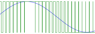
As an example, here is a pulse width modulation of a sine wave, showing how the duty cycle is modified based on the input signal value:

Pulse width modulation of a sine wave
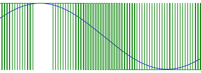
In that example, the square wave is quite slow compared to the wave, in reality, we quite likely use a very high frequency square wave compared to the audible frequencies we want to output, so it would look more like this:

High frequency pulse width modulation of a sine wave
One final thing that simplifies this, is that if the square wave frequency is much higher than the human ear can hear (about 22khz maximum), then it doesn’t matter if we output it, so we can omit the low pass filtering of our output signal and just bung it straight out the speaker. Most speakers and amplifiers do not respond to such high frequencies anyway, so there is yet another reason not to bother about low pass filtering. You might need to low pass filters if you intend to bung your signal into high end recording equipment that supports 96 or 192khz digital recording, otherwise you will be able to see the square wave, but you should not be able to hear it even then (and 192khz studio setups will almost certainly have better filters built in than anything analog that you stick on the output of your arduino).
So, how to do direct digital synthesis using the Arduino? Essentially, we want to generate a very high frequency square wave, with a variable duty cycle. Handily, the ATMEGA processor used in the Arduino has two very useful functions which will let us do exactly this, Timer Interrupts, and Pulse Width Modulation.
Timer Interrupts let you set some code to be run repeatedly, many times a second. You can set the speed at which the interrupt is called, and it will just get called at that speed forever. For example, in the code below, I set an interrupt so that my interrupt code (the interrupt routine) is run approximately 32000 times a second.
Pulse Width Modulation (PWM) essentially lets you generate square waves on a pin with a particular duty cycle. The frequency of these square waves can also be set, conveniently in the same units as we use for setting the speed of interrupts.
So, do to direct digital synthesis, we need to:
- Set up PWM so that it is doing a very high frequency square wave.
- Set an interrupt that alters the duty cycle of the square wave. If we run the interrupt function on the same timer that is driving the PWM, then cunningly, for every cycle of the square wave, the interrupt is fired to set a new value to the square wave duty cycle, and voila, we have our direct digital synthesis.
To use this to generate tones, we use what is called a wave table - this is essentially an array, holding the volume values to generate a sound, such as a sine wave. Our interrupt routine simply loops around this wave table, taking a value out of it each cycle, and setting that to the square wave duty cycle, and as if by magic, we get a lovely sound coming out of our Arduino. To alter the pitch, we alter how fast we go round the wave table.
It is important that the wavetable is 256 bytes long, and aligned on a 256 byte boundary, because in the code below, we assume you can loop round the table by just taking the position&0xff.
char sine256[256]  __attribute__ ((aligned(256))) = {
    0 , 3 , 6 , 9 , 12 , 15 , 18 , 21 , 24 , 27 , 30 , 33 , 36 , 39 , 42 , 45 ,
    48 , 51 , 54 , 57 , 59 , 62 , 65 , 67 , 70 , 73 , 75 , 78 , 80 , 82 , 85 , 87 ,
    89 , 91 , 94 , 96 , 98 , 100 , 102 , 103 , 105 , 107 , 108 , 110 , 112 , 113 , 114 , 116 ,
    117 , 118 , 119 , 120 , 121 , 122 , 123 , 123 , 124 , 125 , 125 , 126 , 126 , 126 , 126 , 126 ,
    127 , 126 , 126 , 126 , 126 , 126 , 125 , 125 , 124 , 123 , 123 , 122 , 121 , 120 , 119 , 118 ,
    117 , 116 , 114 , 113 , 112 , 110 , 108 , 107 , 105 , 103 , 102 , 100 , 98 , 96 , 94 , 91 ,
    89 , 87 , 85 , 82 , 80 , 78 , 75 , 73 , 70 , 67 , 65 , 62 , 59 , 57 , 54 , 51 ,
    48 , 45 , 42 , 39 , 36 , 33 , 30 , 27 , 24 , 21 , 18 , 15 , 12 , 9 , 6 , 3 ,
    0 , -3 , -6 , -9 , -12 , -15 , -18 , -21 , -24 , -27 , -30 , -33 , -36 , -39 , -42 , -45 ,
    -48 , -51 , -54 , -57 , -59 , -62 , -65 , -67 , -70 , -73 , -75 , -78 , -80 , -82 , -85 , -87 ,
    -89 , -91 , -94 , -96 , -98 , -100 , -102 , -103 , -105 , -107 , -108 , -110 , -112 , -113 , -114 , -116 ,
    -117 , -118 , -119 , -120 , -121 , -122 , -123 , -123 , -124 , -125 , -125 , -126 , -126 , -126 , -126 , -126 ,
    -127 , -126 , -126 , -126 , -126 , -126 , -125 , -125 , -124 , -123 , -123 , -122 , -121 , -120 , -119 , -118 ,
    -117 , -116 , -114 , -113 , -112 , -110 , -108 , -107 , -105 , -103 , -102 , -100 , -98 , -96 , -94 , -91 ,
    -89 , -87 , -85 , -82 , -80 , -78 , -75 , -73 , -70 , -67 , -65 , -62 , -59 , -57 , -54 , -51 ,
    -48 , -45 , -42 , -39 , -36 , -33 , -30 , -27 , -24 , -21 , -18 , -15 , -12 , -9 , -6 , -3
    };

So, what our interrupt routine looks like is:

1.  Move our pointer into the wave table (faster for higher pitch, or slower for lower pitch).
2.  Retrieve a value out of the wave table.
3.  Set the pulse width modulation duty cycle to the value from the wave table.
To set up an interrupt routine in code, we use the Arduino ISR macro, like this:

ISR(TIMER1_OVF_vect)
    {
      // update sample position (ignore overflow, as
      // we use the top byte to index into a 256 byte buffer
      // and the overflow means it loops through the buffer)

      //oscillator 0 update position
      oscillators[0].phaseAccu+=oscillators[0].phaseStep;
      //oscillator 0 read wave value from the wavetable at that position
      int valOut0=curWave[oscillators[0].phaseAccu>>8]*oscillators[0].volume;

      // write oscillator value to PWM duty cycle for pin 9
      OCR1A=getByteLevel(valOut0);
    }

For multiple oscillators mixed on one pin it is as simple as adding the two values together:

// interrupt for timer 1 overflow (pins 9 and 10)
    // in this, we set the next value for the PWM for those pins
    // ie. we set the sample value
    ISR(TIMER1_OVF_vect)
    {
      // update sample position (ignore overflow, as
      // we use the top byte to index into a 256 byte buffer
      // and the overflow means it loops through the buffer)

      //oscillator 0 update
      oscillators[0].phaseAccu+=oscillators[0].phaseStep;
      int valOut0=curWave[oscillators[0].phaseAccu>>8]*oscillators[0].volume;

      //oscillator 1 update
      oscillators[1].phaseAccu+=oscillators[1].phaseStep;
      int valOut1=curWave[oscillators[1].phaseAccu>>8]*oscillators[1].volume;

      int mixedVal=valOut0+valOut1;

      // write to pin 9 duty cycle
      OCR1A=getByteLevel(mixedVal);
    }

Each interrupt can drive 2 pins, if you want to do stereo, or output one oscillator per pin or something.

// interrupt for timer 1 overflow (pins 9 and 10)
    // in this, we set the next value for the PWM for those pins
    // ie. we set the sample value
    ISR(TIMER1_OVF_vect)
    {
      // update sample position (ignore overflow, as
      // we use the top byte to index into a 256 byte buffer
      // and the overflow means it loops through the buffer)

      //oscillator 0 update
      oscillators[0].phaseAccu+=oscillators[0].phaseStep;
      int valOut0=curWave[oscillators[0].phaseAccu>>8]*oscillators[0].volume;

      //oscillator 1 update
      oscillators[1].phaseAccu+=oscillators[1].phaseStep;
      int valOut1=curWave[oscillators[1].phaseAccu>>8]*oscillators[1].volume;

    // write these two oscillators out
    // to individual pins

    // write oscillator 0 to pin 9 (left channel)
      OCR1A=getByteLevel(valOut0);
      // write oscillator 1 to pin 10 (right channel)
      OCR1B=getByteLevel(valOut1);
    }
A basic example of this is a 4 pin wave synth for arduino which I wrote - this runs 4 independent oscillators on 4 pins, using interrupts 1 and 2 on the Arduino, and demonstrates how to set up the interrupts, change the frequency and volume of the oscillators and all that jazz.
You can also heavily optimise this stuff, in the Arduino Octosynth there is example code for an 8 oscillator version of this, which has the interrupt routine written mostly in assembler. This makes it fast enough that you can also run a resonant filter on the output of the oscillators, or can mix 16 or more oscillators of unfiltered sound into a single pin.
Related themes:
Software and Hardware,
